Earth fault loop impedance calculation pdf Greymouth
Calculation of Earth Fault Loop Impedance Electrical In an electrical system, a ground loop or earth loop occurs when two points of a circuit both intended to be at ground reference potential have a potential between them. This can be caused, for example, in a signal circuit referenced to ground, if enough current is flowing in the ground to cause two points to be at different potentials.
Earth fault loop impedance memberarea.necawa.asn.au
myCableEngineering.com > Cable Fault Calculation. Fault Loop Impedance . Introduction. The fault loop impedance is the most important aspect to take into consideration when designing an electrical circuit. It directly affects the size of the circuit breaker and the size of the cable that can be used on an installation. All electricians have heard of it. However, the author's experience is that, CableCALC Pro software is used to quickly and accurately calculate earth fault loop impedance and earth cable sizes in full compliance with the latest Australian Standards. For resources and information or if you have questions visit our website www.elek.com.au..
earth loop impedance test: main switch 4/6 12. elevated voltage on neutral 10 13. earth electrode resistance (if required) 10 14. insulation resistance 14 15. voltage (main db) no load 14 16. voltage (main db) on load 14 17. voltage at available load (worst condition) 14 18. operation of earth leakage units 15 19. operation of earth leakage The Zs earth fault loop impedance is tested at the furthest point of each circuit. In most cases the circuit breaker needs to be bridged out. The total earth fault loop impedance is measured by plugging a loop tester into a socket outlet, or in some cases with an external earth probe. The value of the earth fault loop impedance is the sum of
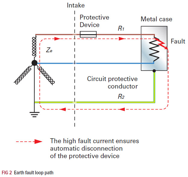
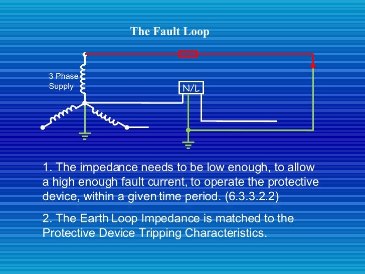
Calculating the maximum allowable earth fault loop impedance. Earth loop impedance is calculated using the following formulae, (BS7671 2008 clause 411.4.5). Zs x Ia ≤ Uo Where: Zs is the earth fault loop impedance in ohms (Ω). Uo is the nominal line voltage to earth in volts (V). The impedance of the protective circuit should be low enough that it allows sufficient fault current to cause the circuit breaker to trip. The regulation is intended to ensure that a protective device will trip within 0.4 seconds if fault current flows in the protective conductor. Calculation of Maximum Allowable Earth Loop Impedance According
The main reason for earth loop impedance testing – which is often simply called loop testing – is to verify that, if a fault occurs in an electrical installation, sufficient current will flow to operate the fuse or circuit breaker protecting the faulty circuit within a predetermined time. The objective is … Fault calculations are one of the most common types of calculation carried out during the design and analysis of electrical systems. These calculations involve determining the current flowing through circuit elements during abnormal conditions – short circuits and earth faults.
the Breaker Earth Loop Impedance (Zs) is calculated as follows; Zs = Uo / Ia Where Uo is the voltage to earth and Ia is the current to trip the breaker in a given breaker disconnection time. Usually we consider two breaker disconnection times: 5 seconds and 0,4 seconds, depending of the application. Earth fault loop impedance NECA Technical have been receiving calls from members about readings obtained in relation to earth fault loop impedance from Network Operator Inspectors. In response to queries we have developed an "Earth Fault Loop Impedance" calculator which …
21/03/2011В В· Zs is your earth fault loop impedance , you take your Ze at the incomming of the supply normally across the main switch , then on each circuit for example a lighting circuit you take your R1&R2 L and CPC joint together at the consumer unit then you add the reading of the Ze and add that to the reading of your R1&R2 and you'll get your Zs but 06/03/2015В В· If your meter cannot measure the earth fault current then measure the loop impedance, take your phase to earth voltage, do the sum and calculate your earth fault current. Your not testing the breaker so breaker size should be irrelevant in the test itself, you are measuring the impedance of the circuit right back to the transformer windings where it comes from.
26/08/2014В В· Divide this value by the expected power factor of the 110V system and there's your earth fault loop impedance value. When working out earth fault loop impedance on the secondary side, the primary side doesn't even come into it. earth loop impedance test: main switch 4/6 12. elevated voltage on neutral 10 13. earth electrode resistance (if required) 10 14. insulation resistance 14 15. voltage (main db) no load 14 16. voltage (main db) on load 14 17. voltage at available load (worst condition) 14 18. operation of earth leakage units 15 19. operation of earth leakage
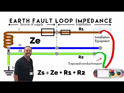
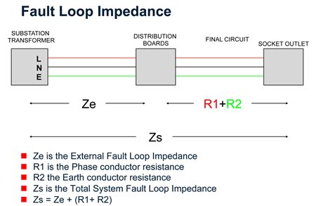
Zs - earth fault loop impedance of the circuit tested Ze - earth fault loop impedance external to the supply (R1+R2) - Sum of the resistance of Line and Earth for the tested circuit. The Earth Fault Loop test sequence: This is a live test so extra care is advised! Step 1. So in short it is the impedance of the earth fault current loop starting and ending at the point of earth fault. This impedance is abbreviated to Zs. This impedance is abbreviated to Zs. The earth fault loop impedance can be used with the supply voltage to calculate the earth-fault current, and hence, to properly determine earth cable size.
21/03/2011В В· Zs is your earth fault loop impedance , you take your Ze at the incomming of the supply normally across the main switch , then on each circuit for example a lighting circuit you take your R1&R2 L and CPC joint together at the consumer unit then you add the reading of the Ze and add that to the reading of your R1&R2 and you'll get your Zs but To check that conventional systems are satisfactory, i.e. that the protection operates on the occurrence of an earth fault, it is necessary to calculate the earth fault loop impedance (Z s) and ensure that the fault current through it will cause the protection to operate.
To check that conventional systems are satisfactory, i.e. that the protection operates on the occurrence of an earth fault, it is necessary to calculate the earth fault loop impedance (Z s) and ensure that the fault current through it will cause the protection to operate. The main reason for earth loop impedance testing – which is often simply called loop testing – is to verify that, if a fault occurs in an electrical installation, sufficient current will flow to operate the fuse or circuit breaker protecting the faulty circuit within a predetermined time. The objective is …
In an electrical system, a ground loop or earth loop occurs when two points of a circuit both intended to be at ground reference potential have a potential between them. This can be caused, for example, in a signal circuit referenced to ground, if enough current is flowing in the ground to cause two points to be at different potentials. More expert advice from the team at ELECSA. This article explains why it is necessary to determine the values of earth fault loop impedance (Zs) for new installations and for those in service that are being inspected and tested to establish their condition. The article also discusses the use of calculation …
MAXIMUM EARTH FAULT LOOP IMPEDANCE VALUES FOR. 06/03/2015 · If your meter cannot measure the earth fault current then measure the loop impedance, take your phase to earth voltage, do the sum and calculate your earth fault current. Your not testing the breaker so breaker size should be irrelevant in the test itself, you are measuring the impedance of the circuit right back to the transformer windings where it comes from., 08/05/2017 · To size CPC and achieve disconnection times as per BS 7671, the lowest possible Earth fault current (Ief) need to be considered in calculations. In Amtech, we need to input either fault current or external earth fault loop impedance to calculate lowest earth fault ….
Fault Calculation Methods University of New South Wales

Distribution Automation Handbook ABB Ltd. Earth fault loop impedance NECA Technical have been receiving calls from members about readings obtained in relation to earth fault loop impedance from Network Operator Inspectors. In response to queries we have developed an "Earth Fault Loop Impedance" calculator which …, The Zs earth fault loop impedance is tested at the furthest point of each circuit. In most cases the circuit breaker needs to be bridged out. The total earth fault loop impedance is measured by plugging a loop tester into a socket outlet, or in some cases with an external earth probe. The value of the earth fault loop impedance is the sum of.
Earth fault loop impedance revision of ENA Engineering. The impedance of the protective circuit should be low enough that it allows sufficient fault current to cause the circuit breaker to trip. The regulation is intended to ensure that a protective device will trip within 0.4 seconds if fault current flows in the protective conductor. Calculation of Maximum Allowable Earth Loop Impedance According, using a earth fault loop impedance tester. You can also determine the earth fault loop impedance by calculation The earth fault loop test makes sure that the protective devices operate within the required time. (anything from 0.05 s to 5 s depending on where and what you are testing) There are a number of ways in which the earth fault loop.
myCableEngineering.com > Cable Fault Calculation
Determining earth fault loop impedance Voltimum UK. 23/08/2016В В· Loop impedance, why it matters and typical values expected for smaller installations (100A or less). Support this channel: Patreon: https://www.patreon.com... MAXIMUM EARTH FAULT LOOP IMPEDANCE VALUES FOR OVERCURRENT PROTECTIVE DEVICES IN COMMON USE, FOR FAULT PROTECTION For fault protection, the limiting values of earth fault loop impedances, Z s, are given in Tables 41.2, 41.3 and 41.4 of BS 7671, for many commonly-used overcurrent protective devices..
In an electrical system, a ground loop or earth loop occurs when two points of a circuit both intended to be at ground reference potential have a potential between them. This can be caused, for example, in a signal circuit referenced to ground, if enough current is flowing in the ground to cause two points to be at different potentials. 22/11/2015 · Use of an RCD/RCBO may give earth fault protection with a relatively high loop impedance, but it wont actually reduce the loop impedance. What are the earthing arrangements of the supply ? If reliant on the general mass of earth, then 5 ohms is good, …
using a earth fault loop impedance tester. You can also determine the earth fault loop impedance by calculation The earth fault loop test makes sure that the protective devices operate within the required time. (anything from 0.05 s to 5 s depending on where and what you are testing) There are a number of ways in which the earth fault loop What is Earth Fault Loop Impedance (EFL)? IEC defined Earth Fault Loop Impedance as The impedance of the earth fault current loop starting and ending at the point of earth fault. This impedance is denoted by the symbol (Zs). Source: City and Guilds: Why knowing its value important? It is important because EFL impedance affects the time for a protective devices to open during fault condition
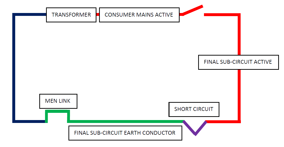
21/03/2011В В· Zs is your earth fault loop impedance , you take your Ze at the incomming of the supply normally across the main switch , then on each circuit for example a lighting circuit you take your R1&R2 L and CPC joint together at the consumer unit then you add the reading of the Ze and add that to the reading of your R1&R2 and you'll get your Zs but The earth fault loop in an MEN system comprises the following components: The protective earthing conductor (PE). The objective of the earth fault loop impedance calculation is to properly determine earth cable size. The neutral return path consisting of the neutral conductor (N) between the main neutral terminal and the transformer neutral point.
What is Earth Fault Loop Impedance (EFL)? IEC defined Earth Fault Loop Impedance as The impedance of the earth fault current loop starting and ending at the point of earth fault. This impedance is denoted by the symbol (Zs). Source: City and Guilds: Why knowing its value important? It is important because EFL impedance affects the time for a protective devices to open during fault condition The main reason for earth loop impedance testing – which is often simply called loop testing – is to verify that, if a fault occurs in an electrical installation, sufficient current will flow to operate the fuse or circuit breaker protecting the faulty circuit within a predetermined time. The objective is …
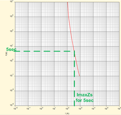
Circuit conditions for which the maximum earth fault loop impedance is calculated are dependant on the system type and selected protective devices. Note: maximum earth fault loop impedance for devices listed in BS 7671 is available for 0.1, 0.2, 0.4, 1 and 5 s maximum disconnect times. the Breaker Earth Loop Impedance (Zs) is calculated as follows; Zs = Uo / Ia Where Uo is the voltage to earth and Ia is the current to trip the breaker in a given breaker disconnection time. Usually we consider two breaker disconnection times: 5 seconds and 0,4 seconds, depending of the application.
Calculations Taking Account of Transformer Impedance. Calculations Concerning Circuits Fed from Sub‐Distribution Boards. Calculations Where Conduit or Trunking is Used as the Protective Conductor. Calculations Where Cable Armouring is Used as the Protective Conductor overall loop impedance from any part of the final circuit installation. Knowing the earth loop impedance, it is possible to calculate the value of the prospective fault current (PFC) at any point in an installation and to ensure that all installed protective devices are of an adequate rating to clear the potential fault current level. Measuring
Calculation of Maximum Earth Loop Impedance Z s For a TN system, section 411.4.5 of BS7671:2008+A3:2015 defines the maximum earth fault loop impedance based on the following condition being met: рќ‘ < рќ‘€ рќђ¶ рќ‘– рќђј Where: Z s maximum earth fault loop impedance. U o minimum voltage factor to take account of voltage variations depending on time and place, changing of transformer taps and earth loop impedance test: main switch 4/6 12. elevated voltage on neutral 10 13. earth electrode resistance (if required) 10 14. insulation resistance 14 15. voltage (main db) no load 14 16. voltage (main db) on load 14 17. voltage at available load (worst condition) 14 18. operation of earth leakage units 15 19. operation of earth leakage
23/08/2016В В· Loop impedance, why it matters and typical values expected for smaller installations (100A or less). Support this channel: Patreon: https://www.patreon.com... earth fault loop impedance but also adequate short-circuit performance must be ensured b y employing the adiabatic equation method from AS/NZS 3008.1.1. CableCALC Pro software is used to quickly and accurately calculate earth fault loop impedance and earth cable sizes in full compliance with the latest Australian Standards.
overall loop impedance from any part of the final circuit installation. Knowing the earth loop impedance, it is possible to calculate the value of the prospective fault current (PFC) at any point in an installation and to ensure that all installed protective devices are of an adequate rating to clear the potential fault current level. Measuring 23/08/2016В В· Loop impedance, why it matters and typical values expected for smaller installations (100A or less). Support this channel: Patreon: https://www.patreon.com...
EARTH LOOP IMPEDANCE: Easily check your Earth Loop Impedance compliance! Here’s how it works, for Single or Three phase cable calculations, simply... 06/03/2015 · If your meter cannot measure the earth fault current then measure the loop impedance, take your phase to earth voltage, do the sum and calculate your earth fault current. Your not testing the breaker so breaker size should be irrelevant in the test itself, you are measuring the impedance of the circuit right back to the transformer windings where it comes from.
01/04/2014 · Click here to send Forum Admin a pdf document for publication on this Topic . Documents must be less than 200k in pdf format . Posted By : Topic: Earth fault loop impedance: MarNissan Mar 28 2014 08:42. Have got an interesting scenario on an off-grid solar install we have done. The impedance on a power point circuit in the house is 2.73 ohms Calculations Taking Account of Transformer Impedance. Calculations Concerning Circuits Fed from Sub‐Distribution Boards. Calculations Where Conduit or Trunking is Used as the Protective Conductor. Calculations Where Cable Armouring is Used as the Protective Conductor
What is the maximum earth fault loop impedance Zs for the
Distribution Automation Handbook ABB Ltd. The main reason for earth loop impedance testing – which is often simply called loop testing – is to verify that, if a fault occurs in an electrical installation, sufficient current will flow to operate the fuse or circuit breaker protecting the faulty circuit within a predetermined time. The objective is …, the Breaker Earth Loop Impedance (Zs) is calculated as follows; Zs = Uo / Ia Where Uo is the voltage to earth and Ia is the current to trip the breaker in a given breaker disconnection time. Usually we consider two breaker disconnection times: 5 seconds and 0,4 seconds, depending of the application..
Understanding Earth Fault Loop Impedance – Electrotechnik
Earth Loop Impedance Test The Illustrated Guide. Earth fault loop impedance (Zs) is the impedance in ohms of the circuit path formed during a fault between earthed metal work and live parts. It includes the external impedance circuit (Ze) and the resistance of the phase and circuit protective conductors (R1 + R2)., To check that conventional systems are satisfactory, i.e. that the protection operates on the occurrence of an earth fault, it is necessary to calculate the earth fault loop impedance (Z s) and ensure that the fault current through it will cause the protection to operate..
Fault Loop Impedance . Introduction. The fault loop impedance is the most important aspect to take into consideration when designing an electrical circuit. It directly affects the size of the circuit breaker and the size of the cable that can be used on an installation. All electricians have heard of it. However, the author's experience is that the operation of Loop Impedance Testers in accordance with AS/NZS Standards and be able to carry out an Earth Fault Loop Impedance test of an installation. COURSE CONTENT • Earth Fault Loop impedance concepts • Associated calculations • Instrument types • The use of testers in the workplace
Fault calculations are one of the most common types of calculation carried out during the design and analysis of electrical systems. These calculations involve determining the current flowing through circuit elements during abnormal conditions – short circuits and earth faults. 01/04/2014 · Click here to send Forum Admin a pdf document for publication on this Topic . Documents must be less than 200k in pdf format . Posted By : Topic: Earth fault loop impedance: MarNissan Mar 28 2014 08:42. Have got an interesting scenario on an off-grid solar install we have done. The impedance on a power point circuit in the house is 2.73 ohms
Earth fault loop impedance revision of ENA Engineering Recommendation P23. By: Eur Ing Graham Kenyon CEng MIET TechIOSH. The Energy Networks Association (ENA) recently published engineering recommendation (ER) P23/2:2018 Guidance on Earth Fault Loop Impedance at Customers’ Intake Supply Terminals, which supersedes ENA ER P23/1:1991 Consumers 23/08/2016 · Loop impedance, why it matters and typical values expected for smaller installations (100A or less). Support this channel: Patreon: https://www.patreon.com...
26/08/2014В В· Divide this value by the expected power factor of the 110V system and there's your earth fault loop impedance value. When working out earth fault loop impedance on the secondary side, the primary side doesn't even come into it. The earth fault-loop impedance in its simplest form is the impedance of the active conductor olus the impedance of the earth conductor. In this case, the fault is a bolted fault, the impedance of which is zero. The maximum disconnection time for a 230 V supply voltage shall not exceed the following:
fault current level. Measuring earth loop impedance Since the AC impedance of a circuit may be different from its DC resistance – particularly for circuit s rated at over100 A – the fault loop impedance is me asured using the same frequency as the nominal mains frequency (50 Hz). The earth loop impedance test measures the resistance of the overall loop impedance from any part of the final circuit installation. Knowing the earth loop impedance, it is possible to calculate the value of the prospective fault current (PFC) at any point in an installation and to ensure that all installed protective devices are of an adequate rating to clear the potential fault current level. Measuring
The impedance of the protective circuit should be low enough that it allows sufficient fault current to cause the circuit breaker to trip. The regulation is intended to ensure that a protective device will trip within 0.4 seconds if fault current flows in the protective conductor. Calculation of Maximum Allowable Earth Loop Impedance According 01/03/2016В В· Session 3, we calculate the R1+R2 of a final circuit, calculate the impedance and read off time current curve to obtain the disconnection times. We'll also compare the time current curves of
CableCALC Pro software is used to quickly and accurately calculate earth fault loop impedance and earth cable sizes in full compliance with the latest Australian Standards. For resources and information or if you have questions visit our website www.elek.com.au. Calculation of Maximum Earth Loop Impedance Z s For a TN system, section 411.4.5 of BS7671:2008+A3:2015 defines the maximum earth fault loop impedance based on the following condition being met: рќ‘ < рќ‘€ рќђ¶ рќ‘– рќђј Where: Z s maximum earth fault loop impedance. U o minimum voltage factor to take account of voltage variations depending on time and place, changing of transformer taps and
the operation of Loop Impedance Testers in accordance with AS/NZS Standards and be able to carry out an Earth Fault Loop Impedance test of an installation. COURSE CONTENT • Earth Fault Loop impedance concepts • Associated calculations • Instrument types • The use of testers in the workplace In an electrical system, a ground loop or earth loop occurs when two points of a circuit both intended to be at ground reference potential have a potential between them. This can be caused, for example, in a signal circuit referenced to ground, if enough current is flowing in the ground to cause two points to be at different potentials.
Zs - earth fault loop impedance of the circuit tested Ze - earth fault loop impedance external to the supply (R1+R2) - Sum of the resistance of Line and Earth for the tested circuit. The Earth Fault Loop test sequence: This is a live test so extra care is advised! Step 1. So in short it is the impedance of the earth fault current loop starting and ending at the point of earth fault. This impedance is abbreviated to Zs. This impedance is abbreviated to Zs. The earth fault loop impedance can be used with the supply voltage to calculate the earth-fault current, and hence, to properly determine earth cable size.
The earth fault loop in an MEN system comprises the following components: The protective earthing conductor (PE). The objective of the earth fault loop impedance calculation is to properly determine earth cable size. The neutral return path consisting of the neutral conductor (N) between the main neutral terminal and the transformer neutral point. So in short it is the impedance of the earth fault current loop starting and ending at the point of earth fault. This impedance is abbreviated to Zs. This impedance is abbreviated to Zs. The earth fault loop impedance can be used with the supply voltage to calculate the earth-fault current, and hence, to properly determine earth cable size.
Fault Loop Impedance . Introduction. The fault loop impedance is the most important aspect to take into consideration when designing an electrical circuit. It directly affects the size of the circuit breaker and the size of the cable that can be used on an installation. All electricians have heard of it. However, the author's experience is that 06/03/2015В В· If your meter cannot measure the earth fault current then measure the loop impedance, take your phase to earth voltage, do the sum and calculate your earth fault current. Your not testing the breaker so breaker size should be irrelevant in the test itself, you are measuring the impedance of the circuit right back to the transformer windings where it comes from.
Earth Fault-Loop Impedance Calculation – Filipino Engineer. Fault calculations are one of the most common types of calculation carried out during the design and analysis of electrical systems. These calculations involve determining the current flowing through circuit elements during abnormal conditions – short circuits and earth faults., MAXIMUM EARTH FAULT LOOP IMPEDANCE VALUES FOR OVERCURRENT PROTECTIVE DEVICES IN COMMON USE, FOR FAULT PROTECTION For fault protection, the limiting values of earth fault loop impedances, Z s, are given in Tables 41.2, 41.3 and 41.4 of BS 7671, for many commonly-used overcurrent protective devices..
MAXIMUM EARTH FAULT LOOP IMPEDANCE VALUES FOR
Loop Impedance YouTube. the operation of Loop Impedance Testers in accordance with AS/NZS Standards and be able to carry out an Earth Fault Loop Impedance test of an installation. COURSE CONTENT • Earth Fault Loop impedance concepts • Associated calculations • Instrument types • The use of testers in the workplace, 08/05/2017 · To size CPC and achieve disconnection times as per BS 7671, the lowest possible Earth fault current (Ief) need to be considered in calculations. In Amtech, we need to input either fault current or external earth fault loop impedance to calculate lowest earth fault ….
Earth Fault Loop Impedance – ConnectUs Electrical Contractors. EARTH LOOP IMPEDANCE: Easily check your Earth Loop Impedance compliance! Here’s how it works, for Single or Three phase cable calculations, simply..., overall loop impedance from any part of the final circuit installation. Knowing the earth loop impedance, it is possible to calculate the value of the prospective fault current (PFC) at any point in an installation and to ensure that all installed protective devices are of an adequate rating to clear the potential fault current level. Measuring.
What is the maximum earth fault loop impedance Zs for the

Fault Calculations Introduction. 01/03/2016В В· Session 3, we calculate the R1+R2 of a final circuit, calculate the impedance and read off time current curve to obtain the disconnection times. We'll also compare the time current curves of The earth fault loop in an MEN system comprises the following components: The protective earthing conductor (PE). The objective of the earth fault loop impedance calculation is to properly determine earth cable size. The neutral return path consisting of the neutral conductor (N) between the main neutral terminal and the transformer neutral point..
23/08/2016В В· Loop impedance, why it matters and typical values expected for smaller installations (100A or less). Support this channel: Patreon: https://www.patreon.com... fault loop impedance, all play critical and interrelated parts in the assessments by the electrical contractor and his suppliers. Fault Loop Impedance: Clearing a short circuit to earth requires a fault current high enough to cause the protective device to operate quickly. AS/NZS 3000:2000 (Clause 1.7.4.3.3) requires
EARTH LOOP IMPEDANCE: Easily check your Earth Loop Impedance compliance! Here’s how it works, for Single or Three phase cable calculations, simply... 22/11/2015 · Use of an RCD/RCBO may give earth fault protection with a relatively high loop impedance, but it wont actually reduce the loop impedance. What are the earthing arrangements of the supply ? If reliant on the general mass of earth, then 5 ohms is good, …
22/11/2015 · Use of an RCD/RCBO may give earth fault protection with a relatively high loop impedance, but it wont actually reduce the loop impedance. What are the earthing arrangements of the supply ? If reliant on the general mass of earth, then 5 ohms is good, … EARTH LOOP IMPEDANCE: Easily check your Earth Loop Impedance compliance! Here’s how it works, for Single or Three phase cable calculations, simply...
interests of efficiency. The magnitude of earth faults currents can be determined in ways in which the system neutral is earthed. Solid neutral earthing means high earth fault currents as this is only limited by the inherent earth fault impedance of the system. By the use of resistance or impedance in the earth loop impedance test: main switch 4/6 12. elevated voltage on neutral 10 13. earth electrode resistance (if required) 10 14. insulation resistance 14 15. voltage (main db) no load 14 16. voltage (main db) on load 14 17. voltage at available load (worst condition) 14 18. operation of earth leakage units 15 19. operation of earth leakage
In an electrical system, a ground loop or earth loop occurs when two points of a circuit both intended to be at ground reference potential have a potential between them. This can be caused, for example, in a signal circuit referenced to ground, if enough current is flowing in the ground to cause two points to be at different potentials. Fault calculation is not simple for a number of reasons: There are many different types of fault in three phase systems . ELEC9713: Industrial and Commercial Power Systems p. 1 The impedance characteristics of all electrical items in the system must be known The fault impedance itself may be non-zero and difficult to estimate There may be substantial fault current contribution from rotating
fault loop impedance, all play critical and interrelated parts in the assessments by the electrical contractor and his suppliers. Fault Loop Impedance: Clearing a short circuit to earth requires a fault current high enough to cause the protective device to operate quickly. AS/NZS 3000:2000 (Clause 1.7.4.3.3) requires the operation of Loop Impedance Testers in accordance with AS/NZS Standards and be able to carry out an Earth Fault Loop Impedance test of an installation. COURSE CONTENT • Earth Fault Loop impedance concepts • Associated calculations • Instrument types • The use of testers in the workplace
earth loop impedance test: main switch 4/6 12. elevated voltage on neutral 10 13. earth electrode resistance (if required) 10 14. insulation resistance 14 15. voltage (main db) no load 14 16. voltage (main db) on load 14 17. voltage at available load (worst condition) 14 18. operation of earth leakage units 15 19. operation of earth leakage Earth fault loop impedance (Zs) is the impedance in ohms of the circuit path formed during a fault between earthed metal work and live parts. It includes the external impedance circuit (Ze) and the resistance of the phase and circuit protective conductors (R1 + R2).
Earth fault loop impedance (Zs) is the impedance in ohms of the circuit path formed during a fault between earthed metal work and live parts. It includes the external impedance circuit (Ze) and the resistance of the phase and circuit protective conductors (R1 + R2). fault loop impedance, all play critical and interrelated parts in the assessments by the electrical contractor and his suppliers. Fault Loop Impedance: Clearing a short circuit to earth requires a fault current high enough to cause the protective device to operate quickly. AS/NZS 3000:2000 (Clause 1.7.4.3.3) requires
Calculation of Maximum Earth Loop Impedance Z s For a TN system, section 411.4.5 of BS7671:2008+A3:2015 defines the maximum earth fault loop impedance based on the following condition being met: рќ‘ < рќ‘€ рќђ¶ рќ‘– рќђј Where: Z s maximum earth fault loop impedance. U o minimum voltage factor to take account of voltage variations depending on time and place, changing of transformer taps and 01/04/2014В В· Click here to send Forum Admin a pdf document for publication on this Topic . Documents must be less than 200k in pdf format . Posted By : Topic: Earth fault loop impedance: MarNissan Mar 28 2014 08:42. Have got an interesting scenario on an off-grid solar install we have done. The impedance on a power point circuit in the house is 2.73 ohms
So in short it is the impedance of the earth fault current loop starting and ending at the point of earth fault. This impedance is abbreviated to Zs. This impedance is abbreviated to Zs. The earth fault loop impedance can be used with the supply voltage to calculate the earth-fault current, and hence, to properly determine earth cable size. So in short it is the impedance of the earth fault current loop starting and ending at the point of earth fault. This impedance is abbreviated to Zs. This impedance is abbreviated to Zs. The earth fault loop impedance can be used with the supply voltage to calculate the earth-fault current, and hence, to properly determine earth cable size.

What is Earth Fault Loop Impedance (EFL)? IEC defined Earth Fault Loop Impedance as The impedance of the earth fault current loop starting and ending at the point of earth fault. This impedance is denoted by the symbol (Zs). Source: City and Guilds: Why knowing its value important? It is important because EFL impedance affects the time for a protective devices to open during fault condition overall loop impedance from any part of the final circuit installation. Knowing the earth loop impedance, it is possible to calculate the value of the prospective fault current (PFC) at any point in an installation and to ensure that all installed protective devices are of an adequate rating to clear the potential fault current level. Measuring