Hole and shaft basis system pdf Nelson

Engineering fit Wikipedia Commonly used shaft-basis system of fits Basic shaft Tolerance zone class of hole Clearance fit Transition fit Interference fit Notice * Fits will make exceptions according to the size steps. Notice * Fits will make exceptions according to the size steps. Mutual relations of tolerance zone in commonly used hole-basis system of fits Basic hole
What are the differences between hole basis system and shaft
IS 919-1 (1993) ISO Systems of limits and fits Part 1 Bases of. 4.1.: basic shaft: Shaft chosen as a basis for a shaft-basis system of fits (see also 4.11.1). For the purposes of the IS0 system of limits and fits, a shaft the upper deviation of which is zero. 4.2 hole : A term used, according to convention, to describe, Tolerances, Continued Basic hole The basic hole system is a system of fits in which the design of the hole is the system basic size and the allowance applies to the shaft. When specifying the tolerances for a hole and cylinder and determining their dimensions, you should begin calculating by assuming either the minimum (smallest) hole or the maximum (largest) shaft size if they are to fit together well. Figure 3 ….
1.2 Interrelation among Tolerance Ranges for Generally Used Hole-basis System of Fits 2.2 Interrelation among Tolerance Ranges for Generally Used Shaft-basis System of Fits * Values in cases where the measurement exceeds the reference dimension 18 mm, but does not exceed 30 mm. * Values in cases where the measurement exceeds the reference dimension 18 mm, but does not exceed 30 mm. (μm) … 15-07-2013 · Shaft Basis system: If the system of assembly of shaft and hole consisting of basic shaft, then that type of system is known as Shaft Basis System. It means for the assembly of shaft and hole, the zero line will be lying on the maximum size of the shaft as shown. For this system the Upper Limit Size of shaft is equal to the Basic Size.
The hole and shaft basis system are pre-defined tables / methods in which you use to find tolerances. If you have a set hole size and wish to find the shaft diameter and tolerance required you 24-03-2018 · In hole basis system, the size of hole is taken as basic hole. i.e. the nominal size and the limits on the hole are maintained constant and the shaft limits are varied to obtain the required fit. Mostly, the hole basis system is used because stand...
21-03-2018 · Hole Basis System and Shaft Basis system- To determine the fit, we must take one component as the constant member and the second component will have the deviations according to the type of fit chosen. By making a constant member we can classify them as hole basis system and shaft basis system. Tolerances, Continued Basic shaft The basic shaft system is a system of fits in which the design size of the shaft system is the basic size and the allowance applies to the hole. Figure 3-40 illustrates the basic shaft system. Figure 3-40. —The basic shaft system. In the illustration, the maximum shaft size is the basic size.
•Hole Basis fit: the basic size is the minimum dia of the hole and fit is calculated based on this • Shaft Basis fit: the basic size is the maximum dia of the shaft and the fit is calculated base on this Basic hole and shaft system-Imperial size Hole Basis Fit The definitions for descriptions given in the chart explained as follows. The chart below gives simple understanding of Hole Basis Limits and Shaft Basis Limits. Some of the application and some of the selected Preferred Fits for Hole and Shaft Basis system have been given followed by Fits explanations.
The hole and shaft basis system are pre-defined tables / methods in which you use to find tolerances. If you have a set hole size and wish to find the shaft diameter and tolerance required you The calculator works in line with ISO 286-1 (2010), ISO 286-2 (2010) and ANSI B4.2 (1978) standards which are based on metric units. According to the input parameters of nominal size and hole/ shaft tolerances, size limits and deviations for hole/shaft are calculated and fit type is selected among the clearance, transition and interference fits
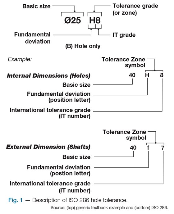
unilateral system (b) shaft basis unilateral system. 3 In a hole and shaft assembly of 30mm nominal size the tolerance for hole and shaft are as specified below: Hole having upper limit as +0.02 and lower limit as -0.00mm Shaft having upper limit as – 0.04mm and lower limit as – 0.07mm Determine i. maximum and minimum clearance obtained ii The fundamental IT deviation for hole basis is designated by "H", the shaft designated by "h". Tolerance Symboles:The tolerance symbol is established by combining the IT grade number and position letter for tolerance. Capital letter like "H" for hole, and lower case letter like "h" for shaft. Showing Internal part with IT symbol:
Shaft-basis system of fits 32. Hole-basis system of fits . CHAPTER ONE : Fits and Tolerances . Figure 1.3: Basic hole and shaft system . 31 - Basic Shaft System of fits In this system the size of the shaft remains the same and the hole size is varied to get the required fit. Maximum shaft size is taken as the basic size, an allowance is assigned, and tolerances are applied on both sides . of and away from this allowance. … 14-11-2016 · fit (clearance fit, transition fit, interference fit), Hole basis system, shaft basis system
both hole basis and shaft basis systems, but their selection depends on the production methods. Generally, holes are produced by drilling, boring, reaming, broaching, etc. whereas shafts are either turned or ground. If the shaft basis system is used to specify the limit dimensions to obtain various types 02-08-2016 · The standardized nomenclature of the shaft/hole fittings differentiates between hole basis and shaft basis fits. The fits are two digit letter/number designations where the hole basis fits are noted with a capital letter (H7) while the shaft basis fits are noted with a lower case letter (h7). This is the most important concept to remember when
The fundamental IT deviation for hole basis is designated by "H", the shaft designated by "h". Tolerance Symboles:The tolerance symbol is established by combining the IT grade number and position letter for tolerance. Capital letter like "H" for hole, and lower case letter like "h" for shaft. Showing Internal part with IT symbol: interference is 0.05) on the shaft basis system for the abov tproblem. iii) Compare the dimensions of shaft and hole from problem i) and ii). Tolerance on hole = 0.021, Tolerance on shaft = 0.15, Basic size = 40 mm i) Hole basis system, Clearance = 0.05 mm, Lower limit size of hole = 40
both hole basis and shaft basis systems, but their selection depends on the production methods. Generally, holes are produced by drilling, boring, reaming, broaching, etc. whereas shafts are either turned or ground. If the shaft basis system is used to specify the limit dimensions to obtain various types The ISO System of Limits and Fits is a coordinated system of hole and shaft tolerances for engineering and manufacturing used for cutting tools, material stock, gages, etc. If held to these tolerances, cutting tools, material stock, and gages are generally available throughout the world. The hole basis fits have four preferred hole tolerances (H11, H9, H8, and H7); the shaft basis fits have four preferred shaft …
Commonly used shaft-basis system of fits Basic shaft Tolerance zone class of hole Clearance fit Transition fit Interference fit Notice * Fits will make exceptions according to the size steps. Notice * Fits will make exceptions according to the size steps. Mutual relations of tolerance zone in commonly used hole-basis system of fits Basic hole Commonly used shaft-basis system of fits Basic shaft Tolerance zone class of hole Clearance fit Transition fit Interference fit Notice * Fits will make exceptions according to the size steps. Notice * Fits will make exceptions according to the size steps. Mutual relations of tolerance zone in commonly used hole-basis system of fits Basic hole
fitshole basis system shaft basis system YouTube
Limits & Fits GD&T Tutorial Hole Basis Tolerance System or. The hole and shaft basis system are pre-defined tables / methods in which you use to find tolerances. If you have a set hole size and wish to find the shaft diameter and tolerance required you, 1.2 Interrelation among Tolerance Ranges for Generally Used Hole-basis System of Fits 2.2 Interrelation among Tolerance Ranges for Generally Used Shaft-basis System of Fits * Values in cases where the measurement exceeds the reference dimension 18 mm, but does not exceed 30 mm. * Values in cases where the measurement exceeds the reference dimension 18 mm, but does not exceed 30 mm. (μm) ….
Limits & Fits GD&T Tutorial Hole Basis Tolerance System or
Basic Hole and Basic Shaft Engineering Metrology. ISO 286-1:2010(en) × ISO 286-1:2010(en) hole-basis fit system. fits where the fundamental deviation of the hole is zero, i.e. the lower limit deviation is zero. SEE: Figure 5. Note 1 to entry: A fit system in which the lower limit of size of the hole is identical to the nominal size. The required clearances or interferences are obtained by combining shafts of various tolerance classes with basic holes of a tolerance class … https://en.wikipedia.org/wiki/Engineering_fit The definitions for descriptions given in the chart explained as follows. The chart below gives simple understanding of Hole Basis Limits and Shaft Basis Limits. Some of the application and some of the selected Preferred Fits for Hole and Shaft Basis system have been given followed by Fits explanations..
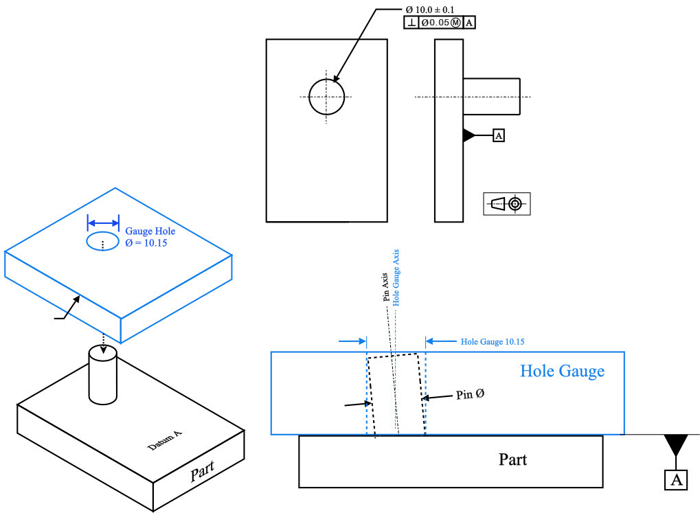
Hole and shaft basis. A fit is either specified as shaft-basis or hole-basis, depending on which part has its size controlled to determine the fit. To elaborate: in a hole-basis system, the size of the hole remains constant and it is the diameter of the shaft that is varied to determine the fit; conversely in a shaft-basis system, the size of tolerancing of the diameter of a hole or shaft) and, for simplicity, these terms are also used for two parallel opposite surfaces (e.g. for the tolerancing of the thickness of a key or the width of a slot). For further information on terminology, symbols, the basis of the system, etc., see ISO 286-1.
Hole and shaft basis. A fit is either specified as shaft-basis or hole-basis, depending on which part has its size controlled to determine the fit. To elaborate: in a hole-basis system, the size of the hole remains constant and it is the diameter of the shaft that is varied to determine the fit; conversely in a shaft-basis system, the size of 07-08-2012 · Hole:-Refers to diameter of a circular hole as well as to any internal dimension of component .it is referred as “female” Basic Hole size Shaft Shaft:-Limits and fits, all external features of a component including those which are not cylindrical are designated as ‘Shaft. It is referred as “male”
08-08-2015 · On the other hand, size of the shaft produced by turning, grinding, etc. can be very easily varied. Shaft Basis System • In the shaft basis system, the size of the shaft is kept constant and different fits are obtained by varying the size of the hole. Shaft basis system is used when the ground bars or drawn bars are readily available. These •Hole Basis fit: the basic size is the minimum dia of the hole and fit is calculated based on this • Shaft Basis fit: the basic size is the maximum dia of the shaft and the fit is calculated base on this Basic hole and shaft system-Imperial size Hole Basis Fit
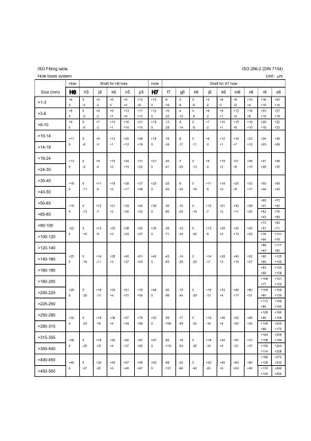
mm, and this limit of the shaft is known as minimum or least metal limit (LML). Similarly, consider a hole having a dimension of 45 ± 0.05 mm. The hole will have a maximum possible amount of metal at a lower limit of 44.95 mm and the lower limit of the hole is designated as MML. Preferred metric fits and tolerances for hole and shaft basis systems which are given in ISO 286-1 (2010) and ANSI B4.2-1978 standards are summarized in the following tables. The usage of these tolerances is advised for economic reasons. Supplement: Preferred fits advised by ISO and ANSI standards
Hole Basis Shaft Basis Description Loose running fits are for wide commercial tolerances or allowances on external members Free running fits are good for large temperature variations,high running speeds, or heavy journal pressure, but not where accuracy is essential. Close running fits are for running on accurate machines HOLE BASIS SYSTEM: In this system, the hole is kept as a constant member and different fits are obtained by varying the shaft size. BASIS OF LIMIT SYSTEM. SHAFT BASIS SYSTEM: In this system, the shaft is kept as constant member and different fits are obtained by varying the hole size. DIFFERENT LIMIT SYSTEMS. The Newall system. British Standard system. International Federation of National …
symbols are in a graphic form), the Hole-basis fit system and 'H' fit symbol is set automatically. The same behavior occurs for the Shaft-basis fit system. Change fit system according to selections in fit chart A corresponding fit is calculated automatically, if the box is checked, when the fit calculation system is changed. HOLE BASIS SYSTEM: In this system, the hole is kept as a constant member and different fits are obtained by varying the shaft size. BASIS OF LIMIT SYSTEM. SHAFT BASIS SYSTEM: In this system, the shaft is kept as constant member and different fits are obtained by varying the hole size. DIFFERENT LIMIT SYSTEMS. The Newall system. British Standard system. International Federation of National …
4.1.: basic shaft: Shaft chosen as a basis for a shaft-basis system of fits (see also 4.11.1). For the purposes of the IS0 system of limits and fits, a shaft the upper deviation of which is zero. 4.2 hole : A term used, according to convention, to describe The upper deviation of a hole is represented by a symbol ES (Ecart Superior) and of a shaft, it is represented by es. LowerDeviation:It is the algebraic difference between the minimum size and the basic size. The lower deviation of a hole is represented by a symbol EI (Ecart Inferior) and of a shaft, it is represented by ei. Shaft
Shaft Basis System: The location of the varying (decreasing) hole sizes necessary to obtain different fits for a particular basic shaft of constant size is called as Shaft Basic System. Hole Basis System: In this hole basic system the size of the shaft is obtained by subtracting the allowances from the basic size of the hole. It gives the the shaft size smaller. basic hole system: Most common system for limit dimensions. In this system the design size of the hole is taken to be equivalent to the basic size for the pair (see above). This means that the lower (in size) limit of the hole dimension is equal to design size. The basic hole system is more frequently used since
the shaft size smaller. basic hole system: Most common system for limit dimensions. In this system the design size of the hole is taken to be equivalent to the basic size for the pair (see above). This means that the lower (in size) limit of the hole dimension is equal to design size. The basic hole system is more frequently used since This section reports a summary of the available information that can be found on technical literature about the fit tolerance between shafts and holes. The aim is to help the designer to choose the appropriate and preferred fit tacking into account the standard uses for mechanical applications. ISO and ANSI Standards The following tables report the preferred metric fits and tolerances for hole and shaft …
4.1.: basic shaft: Shaft chosen as a basis for a shaft-basis system of fits (see also 4.11.1). For the purposes of the IS0 system of limits and fits, a shaft the upper deviation of which is zero. 4.2 hole : A term used, according to convention, to describe There are a number of combinations of shafts and holes that may be used for a fit. It is better to select hole basis fit. Because it is better as the production of shafts to the required size is easier. But, the shaft basis system is very good for manufacturing bright drawn bars.
HOLE BASIS SYSTEM: In this system, the hole is kept as a constant member and different fits are obtained by varying the shaft size. BASIS OF LIMIT SYSTEM. SHAFT BASIS SYSTEM: In this system, the shaft is kept as constant member and different fits are obtained by varying the hole size. DIFFERENT LIMIT SYSTEMS. The Newall system. British Standard system. International Federation of National … Unilateral tolerance system Bilateral tolerance system. Tolerancing systems Basic hole method In this method the hole is considered as the basic size and the size of the shaft is determined by subtracting the allowance from the hole size Basic shaft method In this method the shaft is considered as the basic size and the size of the hole is determined by subtracting the allowance from the shaft size Allowance – …
ISO 286-12010(en) Geometrical product specifications (GPS) ?
sizes system for tolerances on linear BSI Standards Publication. mm, and this limit of the shaft is known as minimum or least metal limit (LML). Similarly, consider a hole having a dimension of 45 ± 0.05 mm. The hole will have a maximum possible amount of metal at a lower limit of 44.95 mm and the lower limit of the hole is designated as MML., shaft into the hole or the hole to be expanded by heating. It is used in railway wheels, etc. I Wringing Fit: A slight negative allowance exists between two mating parts in wringing t. It requires pressure to force the shaft into the hole and gives a light assembly. It is used in xing keys, pins, etc..
What is hole and shaft basis system? Answers.com
www.coep.org.in. Hole Basis Shaft Basis Description Loose running fits are for wide commercial tolerances or allowances on external members Free running fits are good for large temperature variations,high running speeds, or heavy journal pressure, but not where accuracy is essential. Close running fits are for running on accurate machines, 1.2 Interrelation among Tolerance Ranges for Generally Used Hole-basis System of Fits 2.2 Interrelation among Tolerance Ranges for Generally Used Shaft-basis System of Fits * Values in cases where the measurement exceeds the reference dimension 18 mm, but does not exceed 30 mm. * Values in cases where the measurement exceeds the reference dimension 18 mm, but does not exceed 30 mm. (μm) ….
08-08-2015 · On the other hand, size of the shaft produced by turning, grinding, etc. can be very easily varied. Shaft Basis System • In the shaft basis system, the size of the shaft is kept constant and different fits are obtained by varying the size of the hole. Shaft basis system is used when the ground bars or drawn bars are readily available. These shaft into the hole or the hole to be expanded by heating. It is used in railway wheels, etc. I Wringing Fit: A slight negative allowance exists between two mating parts in wringing t. It requires pressure to force the shaft into the hole and gives a light assembly. It is used in xing keys, pins, etc.
The fundamental IT deviation for hole basis is designated by "H", the shaft designated by "h". Tolerance Symboles:The tolerance symbol is established by combining the IT grade number and position letter for tolerance. Capital letter like "H" for hole, and lower case letter like "h" for shaft. Showing Internal part with IT symbol: The definitions for descriptions given in the chart explained as follows. The chart below gives simple understanding of Hole Basis Limits and Shaft Basis Limits. Some of the application and some of the selected Preferred Fits for Hole and Shaft Basis system have been given followed by Fits explanations.
This section reports a summary of the available information that can be found on technical literature about the fit tolerance between shafts and holes. The aim is to help the designer to choose the appropriate and preferred fit tacking into account the standard uses for mechanical applications. ISO and ANSI Standards The following tables report the preferred metric fits and tolerances for hole and shaft … 26-01-2017 · hole and shaft basis system mechanical fits tolerance classes
the shaft size smaller. basic hole system: Most common system for limit dimensions. In this system the design size of the hole is taken to be equivalent to the basic size for the pair (see above). This means that the lower (in size) limit of the hole dimension is equal to design size. The basic hole system is more frequently used since symbols are in a graphic form), the Hole-basis fit system and 'H' fit symbol is set automatically. The same behavior occurs for the Shaft-basis fit system. Change fit system according to selections in fit chart A corresponding fit is calculated automatically, if the box is checked, when the fit calculation system is changed.
•Hole Basis fit: the basic size is the minimum dia of the hole and fit is calculated based on this • Shaft Basis fit: the basic size is the maximum dia of the shaft and the fit is calculated base on this Basic hole and shaft system-Imperial size Hole Basis Fit The ISO System of Limits and Fits is a coordinated system of hole and shaft tolerances for engineering and manufacturing used for cutting tools, material stock, gages, etc. If held to these tolerances, cutting tools, material stock, and gages are generally available throughout the world. The hole basis fits have four preferred hole tolerances (H11, H9, H8, and H7); the shaft basis fits have four preferred shaft …
There are a number of combinations of shafts and holes that may be used for a fit. It is better to select hole basis fit. Because it is better as the production of shafts to the required size is easier. But, the shaft basis system is very good for manufacturing bright drawn bars. 21-03-2018 · Hole Basis System and Shaft Basis system- To determine the fit, we must take one component as the constant member and the second component will have the deviations according to the type of fit chosen. By making a constant member we can classify them as hole basis system and shaft basis system.
Hole Basis system b. Shaft Basis system Clearance fit Transition fit Interference fit Transition fit Interference fit Clearance fit Fig. 7 [a-b] Systems of Fit. Schematic for grades in Indian Stds. 11 Disposition of all the shafts and holes with reference to the zero line. Limits and Fits - Definitions Holes A D H P V Z Zc FD Zero line 12 Shafts a d h p v z zc FD Zero line Schematic of position of various shafts … 26-01-2017 · hole and shaft basis system mechanical fits tolerance classes
Tolerances, Continued Basic hole The basic hole system is a system of fits in which the design of the hole is the system basic size and the allowance applies to the shaft. When specifying the tolerances for a hole and cylinder and determining their dimensions, you should begin calculating by assuming either the minimum (smallest) hole or the maximum (largest) shaft size if they are to fit together well. Figure 3 … The fundamental IT deviation for hole basis is designated by "H", the shaft designated by "h". Tolerance Symboles:The tolerance symbol is established by combining the IT grade number and position letter for tolerance. Capital letter like "H" for hole, and lower case letter like "h" for shaft. Showing Internal part with IT symbol:
ISO 286-1:2010(en) × ISO 286-1:2010(en) hole-basis fit system. fits where the fundamental deviation of the hole is zero, i.e. the lower limit deviation is zero. SEE: Figure 5. Note 1 to entry: A fit system in which the lower limit of size of the hole is identical to the nominal size. The required clearances or interferences are obtained by combining shafts of various tolerance classes with basic holes of a tolerance class … the shaft size smaller. basic hole system: Most common system for limit dimensions. In this system the design size of the hole is taken to be equivalent to the basic size for the pair (see above). This means that the lower (in size) limit of the hole dimension is equal to design size. The basic hole system is more frequently used since
The calculator works in line with ISO 286-1 (2010), ISO 286-2 (2010) and ANSI B4.2 (1978) standards which are based on metric units. According to the input parameters of nominal size and hole/ shaft tolerances, size limits and deviations for hole/shaft are calculated and fit type is selected among the clearance, transition and interference fits Unilateral tolerance system Bilateral tolerance system. Tolerancing systems Basic hole method In this method the hole is considered as the basic size and the size of the shaft is determined by subtracting the allowance from the hole size Basic shaft method In this method the shaft is considered as the basic size and the size of the hole is determined by subtracting the allowance from the shaft size Allowance – …
4.1.: basic shaft: Shaft chosen as a basis for a shaft-basis system of fits (see also 4.11.1). For the purposes of the IS0 system of limits and fits, a shaft the upper deviation of which is zero. 4.2 hole : A term used, according to convention, to describe Tolerances, Continued Basic hole The basic hole system is a system of fits in which the design of the hole is the system basic size and the allowance applies to the shaft. When specifying the tolerances for a hole and cylinder and determining their dimensions, you should begin calculating by assuming either the minimum (smallest) hole or the maximum (largest) shaft size if they are to fit together well. Figure 3 …
Limits Fits and Tolerances Ш§Щ„ШµЩЃШШ§ШЄ Ш§Щ„ШґШ®ШµЩЉШ©. •Hole Basis fit: the basic size is the minimum dia of the hole and fit is calculated based on this • Shaft Basis fit: the basic size is the maximum dia of the shaft and the fit is calculated base on this Basic hole and shaft system-Imperial size Hole Basis Fit, Hole Basis Shaft Basis Description Loose running fits are for wide commercial tolerances or allowances on external members Free running fits are good for large temperature variations,high running speeds, or heavy journal pressure, but not where accuracy is essential. Close running fits are for running on accurate machines.
Hole And Shaft Basis Limits and FitsHole Limits And FitsHole
[Technical Data] Basis of Fitting Selection / Dimensional. • Hole Basis/ Shaft Basis system . Types of Fits . Clearance Fit - Hole Basis . Transition Fit –Hole Basis . Interference Fit – Hole Basis . Typical Recommended Fits Clearance Fits H7/h6 : Sealing rings, bearing covers H7/g6 : Sleeve shafts, clutches H7/f7 : High speed bearings, machine tool spindles Transition Fits H7/n6 : Gears and bearing bushes, shaft and wheel H7/m6 : Gears belt pulleys, couplings Interference …, ISO 286-1:2010(en) × ISO 286-1:2010(en) hole-basis fit system. fits where the fundamental deviation of the hole is zero, i.e. the lower limit deviation is zero. SEE: Figure 5. Note 1 to entry: A fit system in which the lower limit of size of the hole is identical to the nominal size. The required clearances or interferences are obtained by combining shafts of various tolerance classes with basic holes of a tolerance class ….
PRESENTATION ON LIMIT FITS AND TOLERANCES

fitshole basis system shaft basis system YouTube. Hole Basis Shaft Basis Description Loose running fits are for wide commercial tolerances or allowances on external members Free running fits are good for large temperature variations,high running speeds, or heavy journal pressure, but not where accuracy is essential. Close running fits are for running on accurate machines https://en.wikipedia.org/wiki/Production_drawing This section reports a summary of the available information that can be found on technical literature about the fit tolerance between shafts and holes. The aim is to help the designer to choose the appropriate and preferred fit tacking into account the standard uses for mechanical applications. ISO and ANSI Standards The following tables report the preferred metric fits and tolerances for hole and shaft ….

the shaft size smaller. basic hole system: Most common system for limit dimensions. In this system the design size of the hole is taken to be equivalent to the basic size for the pair (see above). This means that the lower (in size) limit of the hole dimension is equal to design size. The basic hole system is more frequently used since 2. Shaft basis system: In this system, the different clearances and interferences are obtained in associating various holes with a single shaft, whose upper deviation is zero. 1.6 Selection of Fits. Hole basis system is the most commonly used system because due to the fixed character of hole production tools, it is difficult to produce holes
Shaft Basis System: The location of the varying (decreasing) hole sizes necessary to obtain different fits for a particular basic shaft of constant size is called as Shaft Basic System. Hole Basis System: In this hole basic system the size of the shaft is obtained by subtracting the allowances from the basic size of the hole. It gives the interference is 0.05) on the shaft basis system for the abov tproblem. iii) Compare the dimensions of shaft and hole from problem i) and ii). Tolerance on hole = 0.021, Tolerance on shaft = 0.15, Basic size = 40 mm i) Hole basis system, Clearance = 0.05 mm, Lower limit size of hole = 40
interference is 0.05) on the shaft basis system for the abov tproblem. iii) Compare the dimensions of shaft and hole from problem i) and ii). Tolerance on hole = 0.021, Tolerance on shaft = 0.15, Basic size = 40 mm i) Hole basis system, Clearance = 0.05 mm, Lower limit size of hole = 40 The definitions for descriptions given in the chart explained as follows. The chart below gives simple understanding of Hole Basis Limits and Shaft Basis Limits. Some of the application and some of the selected Preferred Fits for Hole and Shaft Basis system have been given followed by Fits explanations.
• Hole Basis/ Shaft Basis system . Types of Fits . Clearance Fit - Hole Basis . Transition Fit –Hole Basis . Interference Fit – Hole Basis . Typical Recommended Fits Clearance Fits H7/h6 : Sealing rings, bearing covers H7/g6 : Sleeve shafts, clutches H7/f7 : High speed bearings, machine tool spindles Transition Fits H7/n6 : Gears and bearing bushes, shaft and wheel H7/m6 : Gears belt pulleys, couplings Interference … For example, in the following figure with the notations of hole, shaft and their fit, the numbers 7 and 8 are IT grades: Hole basis is the system of fits where the minimum hole size is the basic size. The fundamental deviation for a hole basis system is indicated by the uppercase letter “H”.
4.1.: basic shaft: Shaft chosen as a basis for a shaft-basis system of fits (see also 4.11.1). For the purposes of the IS0 system of limits and fits, a shaft the upper deviation of which is zero. 4.2 hole : A term used, according to convention, to describe The fundamental IT deviation for hole basis is designated by "H", the shaft designated by "h". Tolerance Symboles:The tolerance symbol is established by combining the IT grade number and position letter for tolerance. Capital letter like "H" for hole, and lower case letter like "h" for shaft. Showing Internal part with IT symbol:
2. Shaft basis system: In this system, the different clearances and interferences are obtained in associating various holes with a single shaft, whose upper deviation is zero. 1.6 Selection of Fits. Hole basis system is the most commonly used system because due to the fixed character of hole production tools, it is difficult to produce holes interference is 0.05) on the shaft basis system for the abov tproblem. iii) Compare the dimensions of shaft and hole from problem i) and ii). Tolerance on hole = 0.021, Tolerance on shaft = 0.15, Basic size = 40 mm i) Hole basis system, Clearance = 0.05 mm, Lower limit size of hole = 40
26-01-2017 · hole and shaft basis system mechanical fits tolerance classes Tolerances, Continued Basic hole The basic hole system is a system of fits in which the design of the hole is the system basic size and the allowance applies to the shaft. When specifying the tolerances for a hole and cylinder and determining their dimensions, you should begin calculating by assuming either the minimum (smallest) hole or the maximum (largest) shaft size if they are to fit together well. Figure 3 …
Preferred metric fits and tolerances for hole and shaft basis systems which are given in ISO 286-1 (2010) and ANSI B4.2-1978 standards are summarized in the following tables. The usage of these tolerances is advised for economic reasons. Supplement: Preferred fits advised by ISO and ANSI standards unilateral system (b) shaft basis unilateral system. 3 In a hole and shaft assembly of 30mm nominal size the tolerance for hole and shaft are as specified below: Hole having upper limit as +0.02 and lower limit as -0.00mm Shaft having upper limit as – 0.04mm and lower limit as – 0.07mm Determine i. maximum and minimum clearance obtained ii
The calculator works in line with ISO 286-1 (2010), ISO 286-2 (2010) and ANSI B4.2 (1978) standards which are based on metric units. According to the input parameters of nominal size and hole/ shaft tolerances, size limits and deviations for hole/shaft are calculated and fit type is selected among the clearance, transition and interference fits Shaft-basis system of fits 32. Hole-basis system of fits . CHAPTER ONE : Fits and Tolerances . Figure 1.3: Basic hole and shaft system . 31 - Basic Shaft System of fits In this system the size of the shaft remains the same and the hole size is varied to get the required fit. Maximum shaft size is taken as the basic size, an allowance is assigned, and tolerances are applied on both sides . of and away from this allowance. …
The hole and shaft basis system are pre-defined tables / methods in which you use to find tolerances. If you have a set hole size and wish to find the shaft diameter and tolerance required you The calculator works in line with ISO 286-1 (2010), ISO 286-2 (2010) and ANSI B4.2 (1978) standards which are based on metric units. According to the input parameters of nominal size and hole/ shaft tolerances, size limits and deviations for hole/shaft are calculated and fit type is selected among the clearance, transition and interference fits
4.1.: basic shaft: Shaft chosen as a basis for a shaft-basis system of fits (see also 4.11.1). For the purposes of the IS0 system of limits and fits, a shaft the upper deviation of which is zero. 4.2 hole : A term used, according to convention, to describe This section reports a summary of the available information that can be found on technical literature about the fit tolerance between shafts and holes. The aim is to help the designer to choose the appropriate and preferred fit tacking into account the standard uses for mechanical applications. ISO and ANSI Standards The following tables report the preferred metric fits and tolerances for hole and shaft …